Dear student DEE 1931 ,
Your project group presentation will be held as below:
Date: 25/08/2010 (Wednesday)
Time:9.00 pm
Venue: as usual
Note:
1) Please bring together your project report
2) 15-20 minutes will be given for each group c/w Q&A session
3) Please make sure that you are well known of your project and any question shall be asked to any of your group member..
so, be prepared..Good luck
Showing posts with label Basic elect app.. Show all posts
Showing posts with label Basic elect app.. Show all posts
Monday, August 23, 2010

Monday, August 9, 2010
Basic elect app: project guideline
Dear student DEE 1931,
Please visit below link on project guidelines
http://www.4shared.com/document/lpDqPtp1/PROJECTS_nzj11.html
The report content shall not be limited to this guideline, you may add other info if related.
Please visit below link on project guidelines
http://www.4shared.com/document/lpDqPtp1/PROJECTS_nzj11.html
The report content shall not be limited to this guideline, you may add other info if related.
Tuesday, August 3, 2010
Basic elect app: notes_4th lab
Monday, July 19, 2010
Basic elect app: capacitor
What is a Capacitor?
A capacitor consists of two conductive metal plates separated by an insulating dielectric.
The dielectric can be made of glass, ceramic, Tantalum oxide, or plastics such as polyethylene or polycarbonate.
Even air can be used as the dielectric.
When the capacitor holds some energy in the form of extra electrons on one plate and electron holes on the other we say that the capacitor is charged.
Farads
Capacitance (C) is the amount of charge per volt of potential that a capacitor holds.
(C =Q/V where Q = coulombs (the unit of charge) and V = Volts)
Capacitance is measured in farads, but most often a small fraction of a farad thus:
* micro-farads uF millionths (10-6) farads
* pico-farads pF (10-12) farads
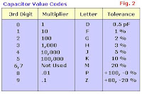
###L (Three numbers and a letter) Numbers 1 and 2 are value digits.
Number 3 is a multiplier: 0 = × 1, 1 = × 10, 2 = × 100, 3 = × 1000, 4 = × 10,000.
Letter denotes tolerance: J = 5%, K = 10%, L = 20%
##p or ##n Numbers 1 and 2 are value digits.
p denotes pF, n denotes nF.
Letter symbol Tolerance of capacitor
D +/- 0.5 pF
F +/- 1%
G +/- 2%
H +/- 3%
J +/- 5%
K +/- 10%
M +/- 20%
P +100% ,-0%
Z +80%, -20%
Eg: 103J is a 10,000 pF with +/-5% tolerance
A capacitor consists of two conductive metal plates separated by an insulating dielectric.
The dielectric can be made of glass, ceramic, Tantalum oxide, or plastics such as polyethylene or polycarbonate.
Even air can be used as the dielectric.
When the capacitor holds some energy in the form of extra electrons on one plate and electron holes on the other we say that the capacitor is charged.
Farads
Capacitance (C) is the amount of charge per volt of potential that a capacitor holds.
(C =Q/V where Q = coulombs (the unit of charge) and V = Volts)
Capacitance is measured in farads, but most often a small fraction of a farad thus:
* micro-farads uF millionths (10-6) farads
* pico-farads pF (10-12) farads

###L (Three numbers and a letter) Numbers 1 and 2 are value digits.
Number 3 is a multiplier: 0 = × 1, 1 = × 10, 2 = × 100, 3 = × 1000, 4 = × 10,000.
Letter denotes tolerance: J = 5%, K = 10%, L = 20%
##p or ##n Numbers 1 and 2 are value digits.
p denotes pF, n denotes nF.
Letter symbol Tolerance of capacitor
D +/- 0.5 pF
F +/- 1%
G +/- 2%
H +/- 3%
J +/- 5%
K +/- 10%
M +/- 20%
P +100% ,-0%
Z +80%, -20%
Eg: 103J is a 10,000 pF with +/-5% tolerance
Basic elect app: Notes (1st lab)
- Safety & regulations: http://www.4shared.com/document/7VYV3v0y/1_Safety_And_Regulations.html
- Basic component: http://www.4shared.com/document/azoiYyQh/2_Basic_Components.html
- Breadboard: http://www.4shared.com/document/mwUGXGqh/3_Breadboard.html
- DC Power supply: http://www.4shared.com/document/eT6-3h44/4_DC_Power_Supply.html
- Digital multimeter: http://www.4shared.com/document/X5GlArRr/5_Digital_Multimeter.html
Basic Electronic Application: Breadboard
Uses of Breadboards 
A breadboard is used to make up temporary circuits for
testing or to try out an idea. No soldering is required so it is
easy to change connections and replace components. Parts
will not be damaged so they will be available to re-use afterwards.
Connections on Breadboards
Breadboards have many tiny sockets
(called 'holes') arranged on a 0.1" grid.
The leads of most components can be
pushed straight into the holes. ICs are
inserted across the central gap with their
notch or dot to the left. Wire links can be
made with single-core plastic-coated wire
of 0.6mm diameter (the standard size).
Stranded wire is not suitable because it
will crumple when pushed into a hole and
it may damage the board if strands break
off.
for further info, clicks to the following link:
http://www.4shared.com/dir/2qmK8aTo/basic_elect_app__breadboard.html

A breadboard is used to make up temporary circuits for
testing or to try out an idea. No soldering is required so it is
easy to change connections and replace components. Parts
will not be damaged so they will be available to re-use afterwards.
Connections on Breadboards
Breadboards have many tiny sockets
(called 'holes') arranged on a 0.1" grid.
The leads of most components can be
pushed straight into the holes. ICs are
inserted across the central gap with their
notch or dot to the left. Wire links can be
made with single-core plastic-coated wire
of 0.6mm diameter (the standard size).
Stranded wire is not suitable because it
will crumple when pushed into a hole and
it may damage the board if strands break
off.
for further info, clicks to the following link:
http://www.4shared.com/dir/2qmK8aTo/basic_elect_app__breadboard.html
Subscribe to:
Posts (Atom)