DEE 1931: Basic Electronic Application (Theory test 1)
Date: 29-July-10
Time: 2.00 pm (1 hour)
Venue: F03
Hint:
1) Design question using 7-segment common cathode
2) Calculate oscilloscope sawtooth signal
3) Determine value by code
Wednesday, July 28, 2010
Tuesday, July 20, 2010
Monday, July 19, 2010
Basic elect app: 1st quiz
Dear students (DEE 1931),
Please be informed that your 1st quiz will be held as below:
Date: 22/07/2010
Venue: F03
Time: 2.00 pm sharp
Duration: 10 -15 minutes
Quiz guideline/ indication:-
1) What is definition of .................
2) What is the purpose of ...............
3) Steps to measure ..........
Please be there on time.
Late comers will not be entertained.
Basic elect app: capacitor
What is a Capacitor?
A capacitor consists of two conductive metal plates separated by an insulating dielectric.
The dielectric can be made of glass, ceramic, Tantalum oxide, or plastics such as polyethylene or polycarbonate.
Even air can be used as the dielectric.
When the capacitor holds some energy in the form of extra electrons on one plate and electron holes on the other we say that the capacitor is charged.
Farads
Capacitance (C) is the amount of charge per volt of potential that a capacitor holds.
(C =Q/V where Q = coulombs (the unit of charge) and V = Volts)
Capacitance is measured in farads, but most often a small fraction of a farad thus:
* micro-farads uF millionths (10-6) farads
* pico-farads pF (10-12) farads
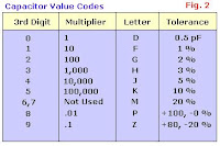
###L (Three numbers and a letter) Numbers 1 and 2 are value digits.
Number 3 is a multiplier: 0 = × 1, 1 = × 10, 2 = × 100, 3 = × 1000, 4 = × 10,000.
Letter denotes tolerance: J = 5%, K = 10%, L = 20%
##p or ##n Numbers 1 and 2 are value digits.
p denotes pF, n denotes nF.
Letter symbol Tolerance of capacitor
D +/- 0.5 pF
F +/- 1%
G +/- 2%
H +/- 3%
J +/- 5%
K +/- 10%
M +/- 20%
P +100% ,-0%
Z +80%, -20%
Eg: 103J is a 10,000 pF with +/-5% tolerance
Basic elect app: Notes (1st lab)
- Safety & regulations: http://www.4shared.com/document/7VYV3v0y/1_Safety_And_Regulations.html
- Basic component: http://www.4shared.com/document/azoiYyQh/2_Basic_Components.html
- Breadboard: http://www.4shared.com/document/mwUGXGqh/3_Breadboard.html
- DC Power supply: http://www.4shared.com/document/eT6-3h44/4_DC_Power_Supply.html
- Digital multimeter: http://www.4shared.com/document/X5GlArRr/5_Digital_Multimeter.html
Basic Electronic Application: Breadboard
Uses of Breadboards 
A breadboard is used to make up temporary circuits for
testing or to try out an idea. No soldering is required so it is
easy to change connections and replace components. Parts
will not be damaged so they will be available to re-use afterwards.
Connections on Breadboards
Breadboards have many tiny sockets
(called 'holes') arranged on a 0.1" grid.
The leads of most components can be
pushed straight into the holes. ICs are
inserted across the central gap with their
notch or dot to the left. Wire links can be
made with single-core plastic-coated wire
of 0.6mm diameter (the standard size).
Stranded wire is not suitable because it
will crumple when pushed into a hole and
it may damage the board if strands break
off.
for further info, clicks to the following link:
http://www.4shared.com/dir/2qmK8aTo/basic_elect_app__breadboard.html
Tuesday, July 13, 2010
Lab cancelled
Dear Student DEE1931
Your lab for the following date will be cancelled due to Germany Day as ordered by TNC
Date: 15-July-2010 (Thursday)
Lab will be as usual for next week (21-July-2010)
Your lab for the following date will be cancelled due to Germany Day as ordered by TNC
Date: 15-July-2010 (Thursday)
Lab will be as usual for next week (21-July-2010)
Sunday, July 11, 2010
Announcement!!
Attn: Diploma student
Your basic electronic application lab (DEE 1931) will be held as below:
Date: Wednesday (14-July-2010)
Time: 9.00 am
Venue: Lab F3 (Level 2, Block 1)
Your attendance is compulsory.
Please let your friends know about this.
Your basic electronic application lab (DEE 1931) will be held as below:
Date: Wednesday (14-July-2010)
Time: 9.00 am
Venue: Lab F3 (Level 2, Block 1)
Your attendance is compulsory.
Please let your friends know about this.
Subscribe to:
Posts (Atom)